- 您现在的位置:买卖IC网 > Sheet目录473 > MAX2831EVKIT+ (Maxim Integrated)KIT EVAL FOR MAX2831
2.4GHz to 2.5GHz 802.11g/b
RF Transceivers with Integrated PA
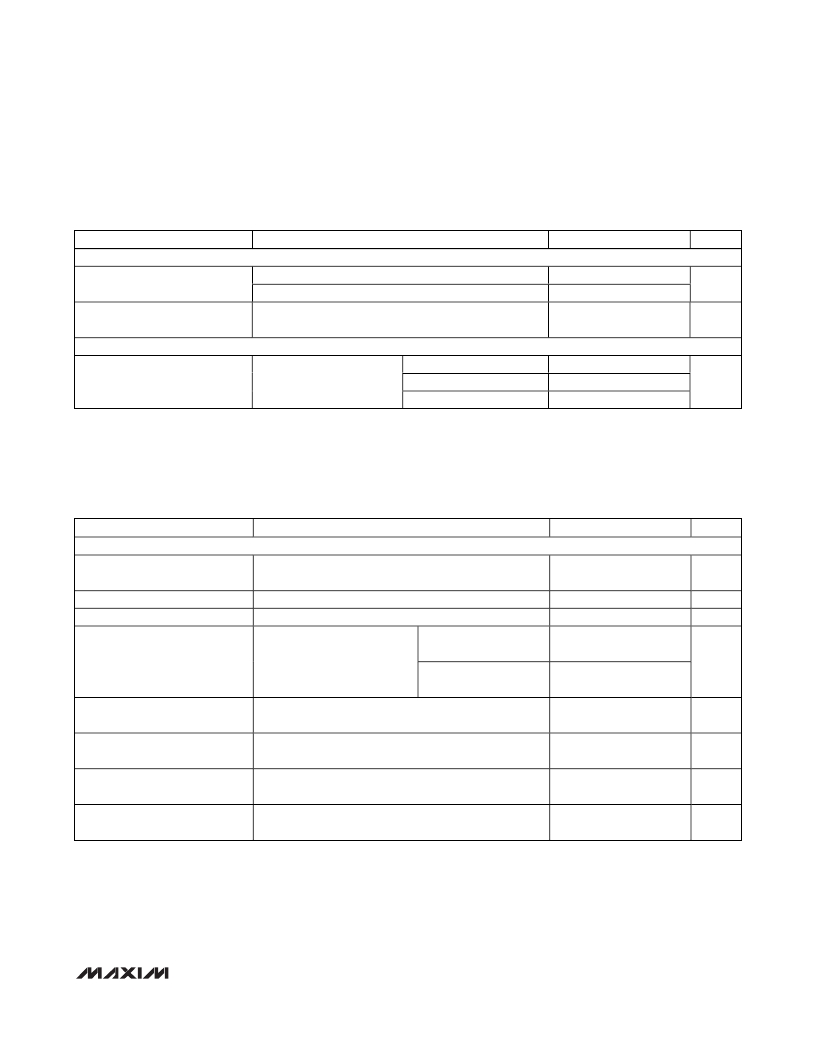
AC ELECTRICAL CHARACTERISTICS—Miscellaneous Blocks
(MAX2831 EV kit: V CC_ = 2.8V, V CCPA = V CCTXPA = 3.3V, f LO = 2.437GHZ, f REF = 40MHz, SHDN = CS = high, SCLK = DIN = low,
and T A = +25°C, unless otherwise noted.) (Note 1)
PARAMETER
CONDITIONS
MIN
TYP
MAX
UNITS
CRYSTAL OSCILLATOR
On-Chip Tuning Capacitance
Range
On-Chip Tuning Capacitance
Step Size
Maximum capacitance, A3:A0 = 1110, D6:D0 = 1111111
Minimum capacitance, A3:A0 = 1110, D6:D0 = 0000000
15.4
0.5
0.12
pF
pF
ON-CHIP TEMPERATURE SENSOR
T A = -40°C
0.35
Output Voltage
A3:A0 = 1000, D9:D8 = 01
T A = +25°C
1
V
T A = +85°C
1.6
AC ELECTRICAL CHARACTERISTICS—Timing
(MAX2831 EV kit: V CC_ = 2.8V, V CCPA = V CCTXPA = 3.3V, T A =+25°C, f LO = 2.437GHz, f REF = 40MHz, SHDN = CS = high, SCLK =
DIN = low, PLL loop bandwidth = 150kHz, and T A = +25°C, unless otherwise noted.) (Note 1)
PARAMETER
CONDITIONS
MIN
TYP
MAX
UNITS
SYSTEM TIMING (See Figure 3)
Turn-On Time
Crystal Oscillator Turn-On Time
Channel Switching Time
Rx/Tx Turnaround Time
Tx Turn-On Time (from Standby
Mode)
Tx Turn-Off Time (from Standby
Mode)
Rx Turn-On Time (from Standby
Mode)
Rx Turn-Off Time (from Standby
Mode)
From SHDN rising edge to LO settled within 1kHz using
external reference frequency input
90% of final output amplitude level
Loop BW = 150kHz, f RF = 2.5GHz to 2.4GHz
Measured from Tx or Rx
Rx to Tx
enable rising edge; signal
settling to within ±2dB of
Tx to Rx, RXHP = 1
steady state
From Tx-enable active rising edge; signal settling to
within ±2dB of steady state
From Tx-enable inactive rising edge
From Rx-enable active rising edge; signal settling to
within ±2dB of steady state
From Rx-enable inactive rising edge
60
1
25
2
2
1.5
1
1.9
0.1
μs
ms
μs
μs
μs
μs
μs
μs
_______________________________________________________________________________________
9
发布紧急采购,3分钟左右您将得到回复。
相关PDF资料
MAX2837EVKIT+
KIT EVAL FOR MAX2837
MAX2838EVKIT+
KIT EVAL FOR MAX2838
MAX2839ASEVKIT+
KIT EVAL FOR MAX2839A WLP
MAX2839EVKIT+
KIT EVAL FOR MAX2839
MAX2851ITK+
TRANSMITTER MIMO 5GHZ 5CH 68TQFN
MAX2852ITK+
IC RECEIVER DFS 5GHZ 68TQFN
MAX2870EVKIT#
EVAL KIT MAX2870
MAX2904EVKIT
EVAL KIT
相关代理商/技术参数
MAX2832ETM+
制造商:Maxim Integrated Products 功能描述:2.4GHZ TO 2.5GHZ, 802.11G RF TRANSCEIVER 制造商:Maxim Integrated Products 功能描述:IC+MAX2832ETM+ - Rail/Tube
MAX2832ETM+CFK
制造商:Maxim Integrated Products 功能描述:2.4GHZ TO 2.5GHZ, 802.11G RF TRANSCEIVERS WITH INTEGRATED PA - Rail/Tube
MAX2832ETM+T
制造商:Maxim Integrated Products 功能描述:2.4GHZ TO 2.5GHZ, 802.11G RF TRANSCEIVER 制造商:Maxim Integrated Products 功能描述:2.4GHZ TO 2.5GHZ, 802.11G RF TRANSCEIVERS WITH INTEGRATED PA - Tape and Reel
MAX2832ETM+TCFK
制造商:Maxim Integrated Products 功能描述:2.4GHZ TO 2.5GHZ, 802.11G RF TRANSCEIVERS WITH INTEGRATED PA - Tape and Reel
MAX2832EVKIT+
功能描述:WiFi/802.11开发工具 MAX2832 Eval Kit RoHS:否 制造商:Roving Networks 产品:Evaluation Boards 工具用于评估:RN-171 支持协议:802.11 b/g 频率:2.4 GHz 接口类型:UART 工作电源电压:2 V to 16 V
MAX2837ETM+
功能描述:射频收发器 2.3-2.7GHz Wireless Broadband RF Txr RoHS:否 制造商:Atmel 频率范围:2322 MHz to 2527 MHz 最大数据速率:2000 Kbps 调制格式:OQPSK 输出功率:4 dBm 类型: 工作电源电压:1.8 V to 3.6 V 最大工作温度:+ 85 C 接口类型:SPI 封装 / 箱体:QFN-32 封装:Tray
MAX2837ETM+T
功能描述:射频收发器 2.3-2.7GHz Wireless Broadband RF Txr RoHS:否 制造商:Atmel 频率范围:2322 MHz to 2527 MHz 最大数据速率:2000 Kbps 调制格式:OQPSK 输出功率:4 dBm 类型: 工作电源电压:1.8 V to 3.6 V 最大工作温度:+ 85 C 接口类型:SPI 封装 / 箱体:QFN-32 封装:Tray
MAX2837EVKIT+
功能描述:WiFi/802.11开发工具 MAX2837 Eval Kit RoHS:否 制造商:Roving Networks 产品:Evaluation Boards 工具用于评估:RN-171 支持协议:802.11 b/g 频率:2.4 GHz 接口类型:UART 工作电源电压:2 V to 16 V
